The 74LS86 (also known as 7486) is a TTL integrated circuit that contains four independent two-input XOR (Exclusive-OR) logic gates. It is powered with +5V (4.75–5.25V), and each gate performs the Boolean operation Y = A ⊕ B. The output is "1" (HIGH) only when its inputs are different. If the inputs are the same (both "0" or both "1"), the output is "0" (LOW).
This component is fundamental in arithmetic circuits, data comparators, and parity generators.
What is the 74LS86?
The 74LS86 is a quad low-power XOR gate (LS series). Its main features are:
- Four independent two-input XOR gates.
- Low power consumption.
- Compatible with standard TTL logic levels (5V).
- Ideal for comparison logic and arithmetic operations.
Basic Operation and Truth Table
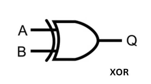
Each XOR gate in the 74LS86 implements the "Exclusive-OR" function. The output is activated only if one, and only one, of the inputs is active.
Truth table for each XOR gate:
| Input A | Input B | Output Y |
|---|
| 0 | 0 | 0 |
| 0 | 1 | 1 |
| 1 | 0 | 1 |
| 1 | 1 | 0 |
Internal operation: Like other ICs in the TTL LS family, it uses transistors for efficient switching with a typical propagation delay of ~13 ns.
Pinout and Connections
The 74LS86 uses the same DIP-14 package and pinout as other common quad gates like the 7400, 7408, and 7432:
- Pin 7: GND (Ground)
- Pin 14: VCC (+5V)
- Gates organized as follows:
- Gate 1: Inputs (Pin 1, 2), Output (Pin 3)
- Gate 2: Inputs (Pin 4, 5), Output (Pin 6)
- Gate 3: Inputs (Pin 9, 10), Output (Pin 8)
- Gate 4: Inputs (Pin 12, 13), Output (Pin 11)
Detailed Technical Specifications
| Specification | Parameter (74LS86) |
|---|
| Logic Function | XOR (Exclusive-OR) |
| Number of gates | 4 (Quad) |
| Inputs per gate | 2 |
| Supply Voltage | 4.75 – 5.25 V |
| Technology | TTL 74LS family (LS-TTL) |
| Output Current (I<sub>OL</sub>) | up to 8 mA (low level) |
| Output Current (I<sub>OH</sub>) | –0.4 mA (high level) |
| Typical Delay (t<sub>pd</sub>) | ~13 ns (propagation) |
| Operating T<sub>range</sub> | 0 °C to 70 °C |
Component Variants
- SN7486/SN74LS86: TTL versions.
- SN74HC86: High-speed CMOS version, operates from 2V to 6V. It is ideal for low-power systems.
- SN74HCT86: CMOS version with TTL-compatible inputs, perfect for integrating 3.3V and 5V logic.
Practical Applications
The XOR gate is very useful for comparison and arithmetic tasks:
- Logical comparator: An XOR output will be "1" if the input bits are different, acting as a 1-bit comparator.
- Binary adder (Half-Adder): A two-bit adder can be built with an XOR gate (for the sum) and an AND gate (for the carry).
- Parity generator/checker: Chains of XOR gates are used to count the number of "1s" in a binary data, useful for error detection.
- Controlled inverter: If one input of the XOR is held at "1", the gate acts as an inverter for the other input.
Practical Resources
- Datasheet SN74LS86 (Texas Instruments): [Quad 2-Input XOR Gates]
- Datasheet SN74HC86 (Texas Instruments): [Quad 2-Input XOR Gates - CMOS]
- Simulations: Tinkercad, Falstad, and other simulators are excellent for building and testing adder or comparator circuits with the 7486.
Frequently Asked Questions (FAQ)
What gate is the 7486?
The 7486 (or 74LS86) is an integrated circuit with four two-input XOR (Exclusive-OR) logic gates.
What is the truth table for the 7486?
The output is 1 if the inputs are different (0 and 1, or 1 and 0). The output is 0 if the inputs are the same (0 and 0, or 1 and 1).
What does the 7486 integrated circuit do?
It performs the XOR logic operation. It is commonly used for comparing bits, in binary adders, and in parity circuits.
What voltage does the 74LS86 operate at?
It operates at a standard TTL voltage of 5V (range 4.75–5.25V).
How do you use an XOR gate as an inverter?
Connect one of the inputs to a HIGH logic level (1). The other input will act as the inverter's input, and the output will be its negated value.
What do SN74LS86, 74HC86, etc., mean?
They are different logic families: 74LS86 (TTL Low-Power Schottky), 74HC86 (High-speed CMOS), and 74HCT86 (CMOS with TTL-compatible inputs). All perform the XOR function but with different electrical characteristics.
References: Information is based on official datasheets from Texas Instruments and digital electronics technical guides.